


| Our Enterprise | NMRV025 | NMRV030 | NMRV040 | NMRV050 | NMRV063 | NMRV075 | NMRV090 | NMRV110 | NMRV130 | NMRV150 |
| NMV030 | NMV040 | NMV050 | NMV063 | NMV075 | NMV090 | NMV110 | NMV130 | NMV150 | ||
| Domestic | NMRV025 | NMRV030 | NMRV040 | NMRV050 | NMRV063 | NMRV075 | NMRV090 | NMRV110 | NMRV130 | NMRV150 |
| NRV030 | NRV040 | NRV050 | NRV063 | NRV075 | NRV090 | NRV110 | NRV130 | NRV150 | ||
| WJ25 | WJ30 | WJ40 | WJ50 | WJ63 | WJ75 | WJ90 | WJ110 | WJ130 | WJ150 | |
| FCNDK25 | FCNDK30 | FCNDK40 | FCNDK50 | FCNDK63 | FCNDK75 | FCNDK90 | FCNDK110 | FCNDK130 | FCNDK150 | |
| FCNK30 | FCNK40 | FCNK50 | FCNK63 | FCNK75 | FCNK90 | FCNK110 | FCNK130 | FCNK150 | ||
| JRSTD025 | JRSTD030 | JRSTD040 | JRSTD050 | JRSTD063 | JRSTD075 | JRSTD090 | JRSTD110 | JRSTD130 | JRSTD150 | |
| JRST030 | JRST040 | JRST050 | JRST063 | JRST075 | JRST090 | JRST110 | JRST130 | JRST150 |
| NMRV-063-30-VS-F1 (FA)-AS-80B5-0.55kW-B3 | |||
| NMRV | Worm gear speed reducer | ||
| NRV | Worm gear speed reducer (Mounting input shaft) | ||
| 63 | Center distance | ||
| 30 | Reduction ratio | ||
| VS | Double input shaft | F1 (FA) | Output flange |
| AS | Single output shaft | AB | Double output shaft |
| PAM | Fitted for motor coupling | 80B5 | Motor mounting facility |
| 0.55kW | Electric motor power | B3 | Mounting position |
Please read before use:
- Load condition
- Speed of rotation or speed ratio (combination with combined speed reducer can get extra low outputting rotational speed )
- Work circumstance (temperature, humidity, corrosion, etc.)
- Space of installation
Ensure coefficient of work condition K1 and coefficient of revise K2
- According to the table 1, choose machinery loading type A, B, C
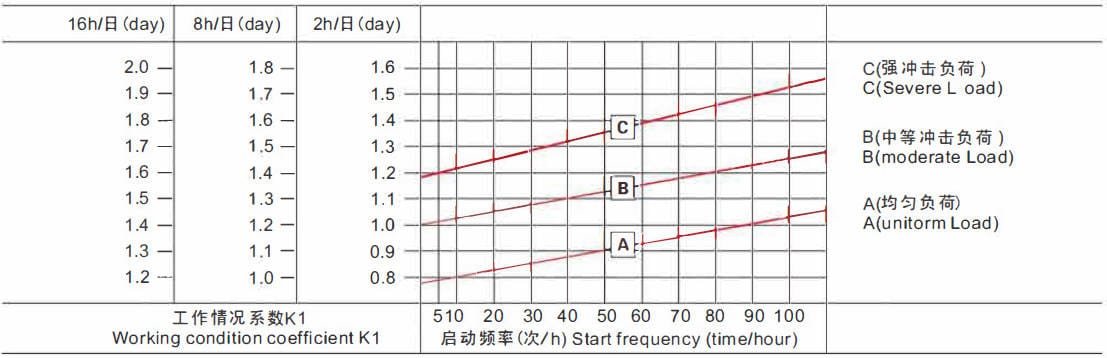
- According to the working time(h/d) and f「equency (times/h ) get the coefficient of work condition K1 from table 1
- According to Table 2, pick up the coefficient of the revised K2
Table 1 Machinery load classification selection
| Using Situation | Example | Load Type |
| Uniform Load | Convey Band (uniform Conveying) | A(uniform Load) |
| Moderate Load | Speed Changed Conveying | B(Moderate Load) |
| Severe Load | Compressor、Pulverizer. etc. | C(Severe Load) |
Table 2 Working condition coefficients K2
| Ambient Temperature | Working Cond巾on Coefficient K2 |
| -10℃~30℃ | 1 |
| 30℃~40℃ | 1.1~1.2 |
Diagram 1 working condition coefficient K1
How to select
- At first, to ensure the value of input machinery load T(torque), multiple K1 and K2 by T, then you can get the value of output torque, on the basis of which, also consider the speed of output rotation or speed ratio, then you can choose a specification
- You can calculate the output torque based on the known input power, reasonable ratio or speed of output rotation, then you can choose specification.
Example for model selection
Ex1. General conveyor belt (uniform load)
- Torque: 19N.m
- Turning time: 8hs/day
- Speed of rotation: about 55r/min
- start frequency: 1 Otimes/h
- Ratio:1/25
- Temperature:25°C (indoor) Connect with motor direct
1. According to Table 1, ensure the type of load
Type of load: load-bearing uniform without impact, choose A;
2. According to diagram 1, choose the point 1 Otimes/h on the intersection A, we can get the K1 =1 of turning time 8hs/d;
3. According to the table 2, get the K2=1;
4. The value of torque is 19 x K1 x K2=19 x 1 x 1=19N.m,choose the closest 19N.m reducer.
Choose selection: NMRV30-1/25
Input power = 0.18kw, the speed of output rotation is= 56r/min,
the value of output torque is 21 N.m
Ex2.con conveying belt( moderate load)
- Torque: 65N.m
- Turning time: 16hs/d
- Speed of rotation: about 21 r/min
- Start frequency: 1 OOtimes/h
- Ratio: 1/60
- Temperature: 35°C (indoor) Connect with motor direct
1 . According to Table 1, ensure the type of load
Type of load: light load-bearing, choose B;
2. According to diagram 1, choose the point 1 OOtimes/h on the intersection B, then you can get the K1 =1.65 of turning time16hs/d;
3. According to the table 2,get the K2= 1.15;
4. The value of torque is 65 x K1 x K2=70 x 1.65 x 1.15=123N.m, choose the closest 123N.m reducer ..
Choose selection: NMRV63-1/60.
Input power = 0.55kw, the speed of output rotation =23.3r/min,the value of output torque is 140N.m
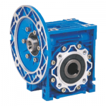
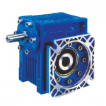
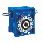
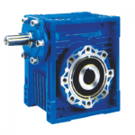
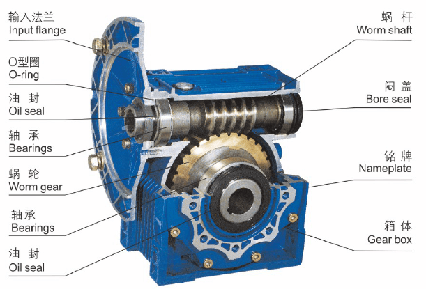
1. Single-Step Worm Gear Reducer
1.1. Models 25-90 use a high-quality aluminum alloy die-cast housing, making them lightweight, compact, and resistant to rust. These models have a small size and light weight, saving installation space.
1.2. Models 110-150 are made of gray cast iron through aluminum mold casting, providing a sturdy and aesthetically pleasing appearance. They can be installed in various orientations.
1.3. These reducers have good heat dissipation, are safe and reliable, and operate efficiently.
1.4. They offer high load capacity, smooth transmission, low vibration, and low noise.
1.5. With a variety of power input and torque output connection structures, they meet different connection needs. The housing design and base hole layout allow for versatile installation methods, providing strong adaptability.
2. Double Step Worm Gear Reducer
2.1. The double step worm gear reducer is formed by combining single step worm gear reducers, offering all the advantages of single step reducers and achieving a larger transmission ratio.
2.2. Common double step combination models include: 25/30, 25/40, 30/40, 30/50, 30/63, 40/75, 40/90, 50/110, 63/130, and 63/150. Users with specific requirements can select models 25, 30, 40, 50, 63, 75, 90, 110, 130, and 150 as combination units for custom configurations.
3. Installation Precautions
3.1. The reducer must be installed on a flat and solid base, and the base bolts must be securely tightened and protected against looseness.
3.2. After installation, the connecting shafts of the prime mover, reducer, and working machine must be precisely aligned to ensure accuracy.
3.3. The outer diameter tolerance of the input and output shafts of the reducer is manufactured according to h6. Couplings, pulleys, sprockets, and other transmission parts should match the appropriate tolerance dimensions to avoid excessive tightness that can damage the bearings or looseness that can affect normal power transmission.
3.4. When installing sprockets, gears, and other transmission parts onto the shaft, they should be positioned as close to the bearing as possible to minimize shaft bending stress.
3.5. When assembling the motor to the reducer, apply grease to the worm head inner bore and keyway to prevent tight assembly and rust over time.
3.6. For direct-coupled reducers with various types of motors, if the motor is heavy, a support device should be installed.
4. Usage Precautions
4.1. Before use, check the reducer’s type, structure, center distance, transmission ratio, input shaft connection method, output shaft structure, input and output shaft orientation, and rotation direction to ensure they meet the requirements. The input speed of the worm gear should not exceed 1500 rpm.
4.2. When starting the machine, the load should be gradually applied and not started at full load.
4.3. Reducers of models 25-90 are equipped with oil filling and draining holes and are pre-filled with ISO VG320 lubricant at the factory, so users do not need to add oil. The oil should be changed after 500 hours of continuous operation and then every 6000 hours thereafter.
4.4. Reducers of models 110-150 have oil filling and draining holes and an oil gauge. They are pre-filled with ISO VG460 mineral lubricant. Users should remove the rubber ring from the breather before use. The oil should be changed after the first 400 hours of operation and every 4000 hours thereafter.
4.5. The maximum allowable oil temperature for the reducer is 85°C. If exceeded, the machine should be stopped for inspection.
4.6. If the reducer has been placed for more than 4-6 months before use and the oil seal has not been immersed in lubricant, it is recommended to replace the oil seal.
4.7. If the operating environment temperature of the reducer exceeds or is lower than the specified temperature range by more than 5°C, please contact our company.


